Maserati - Task 7
Wire the button on the steering wheel
This task is easier with two people.
Note that this is only required for cars that will be operated by hand.
Procedure
UPDATE: Do not attach the capacitor–it is no longer needed.
- Locate the 16” 18-ga duplex wire and remove the foil shielding from both ends.
- Remove 3” of gray sheath from wire.
- Remove foil and bare wire to end of gray sheath.
- On one end of the 16” 18-ga duplex wire:
- Use the wire cutters to cut the black wire 3/8” shorter than the red wire.
- Use the wire strippers to remove 1/4” of insulation from the red wire and the black wire.
- Use the crimp tool to crimp a red , female terminal to the longer wire.
- Use the crimp tool to crimp a red, female terminal to the shorter wires.
- Test the connectors that you just attached by gently pulling on them. They should not slip off.
- On the other end of the 16” 18-ga duplex wire:
- Remove 1/4” of insulation from each of the red and the black wires.
- Twist the strands of each of the bare wires to keep them together. Do not twist the red and black wires together.
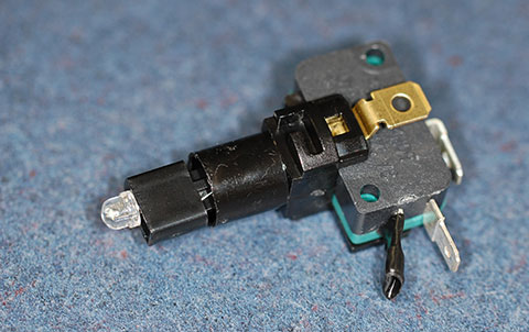
- Locate the switch you removed from the push button.
- Refer to the photo to see how the switch will look when you finish these steps:
- Locate the terminal closest to the black extrusion and bend it down, towards the black extrusion.
- Cover the bent terminal with black vinyl electrical tape.
- Connect the end with the crimped terminals to the switch:
- Connect the crimped terminal attached to the red wire to the metal terminal on the switch that is farthest from the black extrusion.
- Connect the crimped terminal attached to the black wire to the metal terminal that is next to the taped terminal.
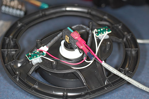
- Replace the switch in the push button by:
- Inserting the switch with the wires oriented along the center spoke of the steering wheel.
- Orient the switch about 1/8 of a turn to the left of center.
- Gently push the switch into the push button and rotate 1/8 of a turn clockwise.
- The switch should snap into place.
- Gently pull on the switch body to see if it comes out. If so, try to insert it again.
- Completed switch assembly.
Verification
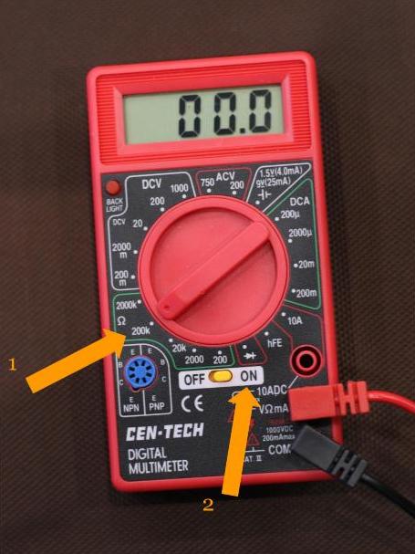
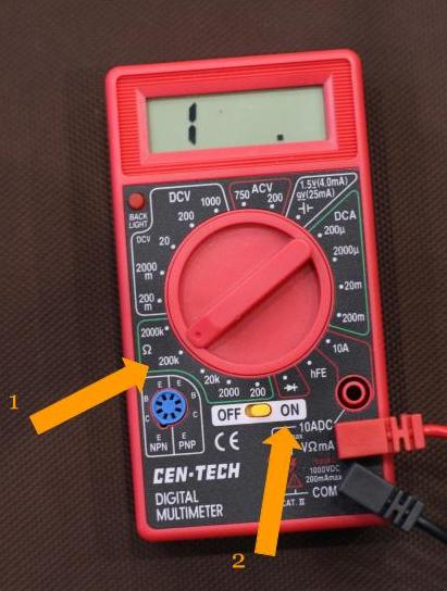
Use the multimeter to test the wiring.
Short video on using the multimeter to measure continuity
-
On the multimeter, select “Ohms” (or continuity). This is usually indicated by the Greek letter omega (Ω) for Ohms.
- Place the red lead of the meter on the bare wire of the red wire.
- Place the black lead of the meter on the bare wire of the black wire.
- With both leads touching their respective terminals as shown in this photo.
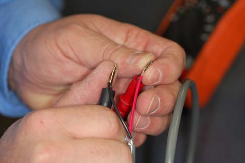
- The meter should not show continuity.
- The meter should indicate continuity (by showing zero or almost zero ohms).

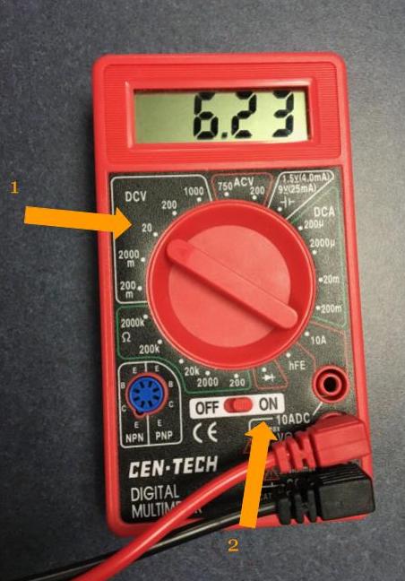
- Check the battery’s voltage.
- After you confirm that the wiring is correct with the multimeter, you can continue to the next task.
- The meter should not show continuity.