Maserati - Task 10
Assemble the toggle switch assembly
Procedure
- Locate the 22” 18-ga duplex wire.
- Remove 3” of gray sheath from wire.
- Remove foil and bare wire to end of gray sheath.
- Clip the bare wire at the end of the gray insulation.
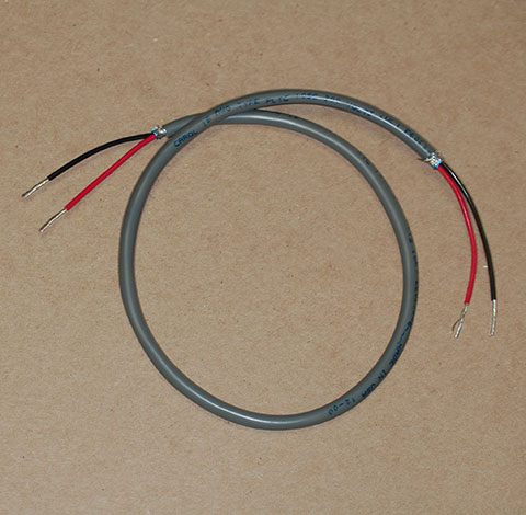
- On both ends of the 22” 18-ga duplex wire, strip 1/2” of the insulation off of the end of each red and black wire. The photo shows how the 22” duplex wire should look after you finish this step.
- Locate the toggle switch and use the #2 Phillips screwdriver to loosen each of the screws on the terminals of the switch.
- On one end of the 22” 18-ga duplex wire, bend the exposed parts of the red and black wires around the shaft of the #1 Phillips screwdriver to form a “J” shape.
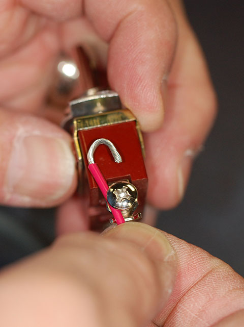
- To the terminal on the side of the switch marked “ON”, attach the red wire to the screw terminal such that the insulated wire extends from the left side of the screw as shown in the preceding photo.
- Use the #2 Phillips screwdriver to tighten the screw to hold the wire.
- To the terminal on the side of the switch marked “OFF”, attach the black wire to the screw terminal such that the wire extends from the left side of the screw.
- Use the #2 Phillips screwdriver to tighten the screw to hold the wire.
Verification
Use the multimeter to test the wiring.
Short video on using the multimeter to measure continuity
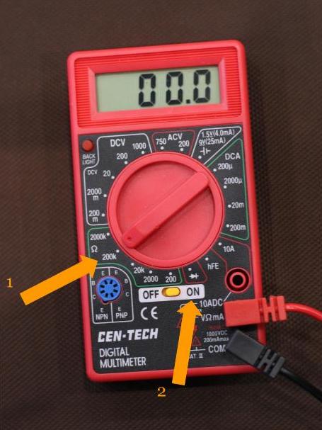
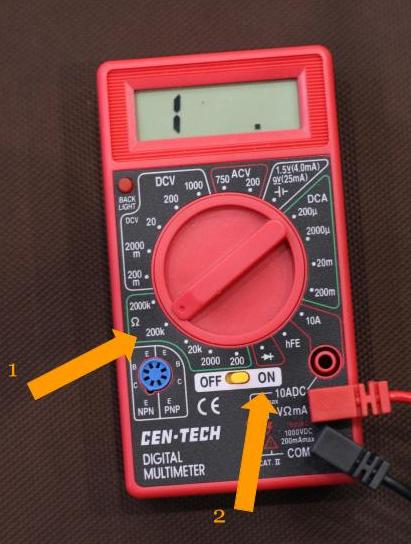
- On the multimeter, select “Ohms” (or continuity). This is usually indicated by the Greek letter omega (Ω) for Ohms.
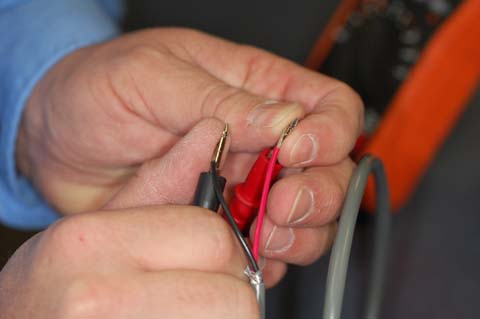
- At the end of the 22” 18-ga duplex wire that’s not connected to the switch:
- Place the red lead of the meter on the bare wire of the red wire.
- Place the black lead of the meter on the bare wire of the black wire.
- With both leads touching their respective wires as shown in this photo
- With the switch in the OFF position, the meter should not show continuity.
- With the switch in the ON position, the meter should indicate continuity (by showing zero or almost zero ohms or beeping).

- With the switch in the OFF position, the meter should not show continuity.
After you confirm that the wiring is correct with the multimeter, you can continue to the next task.