Maserati - Task 12
Connect battery and motor wires
Make sure that the battery has been disconnected before performing this step
UPDATE: One more step has been added below.
Procedure
- Verify that the battery cable is disconnected and stored behind the battery. DO NOT CUT THE BATTERY WIRES.
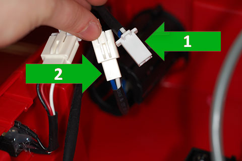
- In the battery compartment, locate the white connectors with two wires: one blue and one white.
- Press the tab on the connectors and separate the two white connector shells.
- One of the connector shells is attached to a cable that goes into the car body (Arrow #1). This is the body-side connector.
- The other connector shell is attached to a cable that connects to a black cylinder (Arrow #2) in the battery compartment. This is the motor-side connector.
- On the motor-side, use the wire cutters to cut the wires as close to the connector as possible.
- On the body-side, use the wire cutters to cut the wires as close to the connector as possible.
- On the body-side wires, while being careful not to nick the blue or white insulation, use your scissors or wire cutters to cut the black tubing back to where the wires enter the battery compartment.
- On each of the blue and white wires that you just cut, use your wire strippers to remove 3/8”-1/2” of the insulation to expose the wire inside.
- On the red and the black wires of the 22” duplex wire that is connected to the toggle switch, remove 3/8”-1/2” of the insulation to expose the wire inside.
- On end of the white, body-side wire, attach one end of a red posi-lock splice. On the other side of that splice, attach the red wire from the 22” duplex wire.
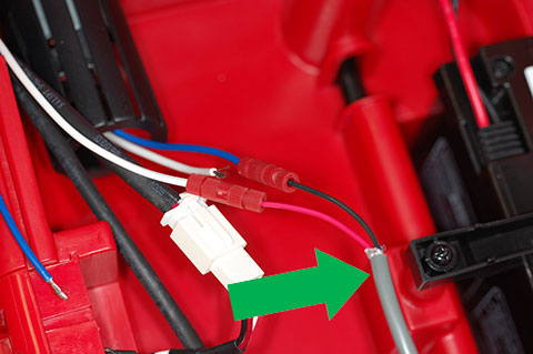
- On the end of the blue, motor-side wire, attach one end of a red posi-lock splice. On the other side of that splice, attach the black wire from the 22” duplex wire. After this step, the ends of the 22” duplex wire (indicated by the arrow) should be connected as shown in the photo.
- Locate the car’s power cable. It is the red and black wires that are connected to the orange connector that was disconnected from the battery cable. REMEMBER: Do not cut the wires that are connected to the battery!
- Remove the black tubing from the car’s power cable to leave about 1” from where the cable goes into the body.
- On the red power wire, about 2” from the body (1” from the end of the black tubing), attach the tap end of a posi-tap connector. To the splice end of that connector, attach the white wire from the motor-side wire.
- On the black power wire, about 1-1/2” from the body (1/2” from the end of the black tubing), attach the tap end of a posi-tap connector. To the splice end of that connector, attach the end of the blue, body-side wire.
-
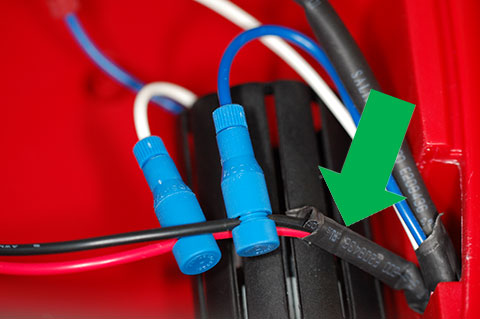
At this point, the power cable wires (inducated by the arrow) and posi-tap connectors should look like the photo.
- Locate the blue and white wires that come out from the motor.
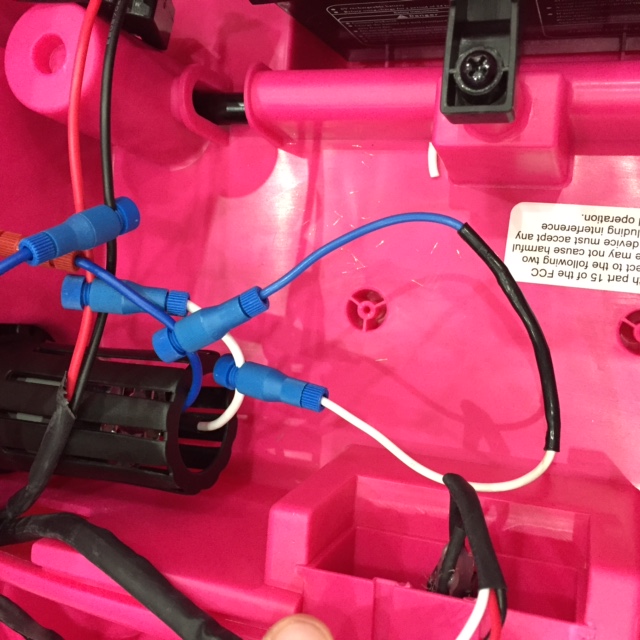
- Attach a blue posi-tap connector to each of the wires that come out of the motor, about 1” from the motor (refer to the photo below).
- On the diode assembly, use the wire stripper to remove about 1/4” of insulation from the blue and the white wires.
- Connect the blue wire from the diode assembly to the posi-tap you connected to the blue wire on the motor.
- Connect the white wire from the diode assembly to the posi-tap you connected to the white wire on the motor.
Verification
Perform these verification tests and steps in the order they are shown here.
Visual confirmation
Visually confirm, and correct as required, the wiring as follows.
- Confirm that the duplex wires are connected as shown in this photo.
- The red duplex wire from the switch is connected through a posi-lock splice to the white, body-side wire.
- The black duplex wire from the switch is connected through a posi-lock splice to the black, motor-side wire.
- Confirm that the power cable connections are correct as shown in this photo.
Electrical test
Note that this is only for RED cars. DO NOT PERFORM THIS TEST ON PINK CARS!!! If you are working on a pink car, continue to the next task from here. If you have a red car, continue with the test.
- Locate the dashboard and place it on top of the car.
- Connect the three-wire connector from the dashboard to the corresponding connector that is coming out of the car.
- Confirm that the toggle switch is OFF.
- In the battery compartment, connect the battery cable to the power cable.
- Locate the cable that was connected to the foot pedal. You should see a black and white wire with connectors and a red wire with a connector that is taped over.
- Set your multimeter to measure DC volts.
- Place the red (+) lead of the meter in the connector on the white wire and place the black (-) lead of the meter in the connector on the black wire.
- The meter should read zero volts (or very close to zero).
- If it does not read zero volts, stop here and check your wiring!
- Press the car’s power button to turn on the car.
- If the multimeter reads zero volts, turn the toggle switch to ON.
- The multimeter should read between 5.5 and 6.5 volts and the minus (-) sign should not be visible.
- If it does not read a positive 6.0 +/- 0.5 volts, stop here and check your wiring!
- Remove the multimeter leads from the connectors.
- Turn the toggle switch to OFF.
- Press the car’s power pushbutton to turn off the car.
Preliminary functional test
- After successful visual and electrical tests, place a block under the car to lift the rear tires off the table so that they are not touching anything. IF THE REAR TIRES ARE IN CONTACT WITH ANYTHING, THE CAR COULD MOVE OFF THE WORK SPACE!
- With the toggle switch OFF, connect the modified steering wheel such that:
- One of the duplex wires is connected to the white foot-pedal wire (that is not coming out of the hole with the dashboard connectors).
- The other duplex wire is connected to the black foot-pedal wire.
- Press the car’s power button to turn on the car.
- Set the toggle switch to ON and make sure the tires do not turn.
- Press the big, red button on the steering wheel.
- Verify the right rear tire is turning clockwise when the big, red button and stops turning when the button is released.
- If the right rear tire does not behave as described, stop here and check your wiring!
Preparation for next task
- Verify the car’s power switch on the dashboard is off.
- Verify the toggle switch is off.
- Disconnect the battery cable connector in the battery compartment and store the connector on the battery cable behind the battery.
- Disconnect the dashboard connectors from the car.
- Remove the blocks holding up the rear of the car; however keep them handy for use in subsequent tasks.
After you confirm that the wiring is correct with the multimeter and that the wheel turns in the correct direction, you can continue to the next task for a red car or the next task for a pink car.